Honeywell VISIONPRO TH8320 User Manual
Browse online or download User Manual for Thermostats Honeywell VISIONPRO TH8320. Honeywell VISIONPRO TH8320 User's Manual
- Page / 40
- Table of contents
- TROUBLESHOOTING
- BOOKMARKS
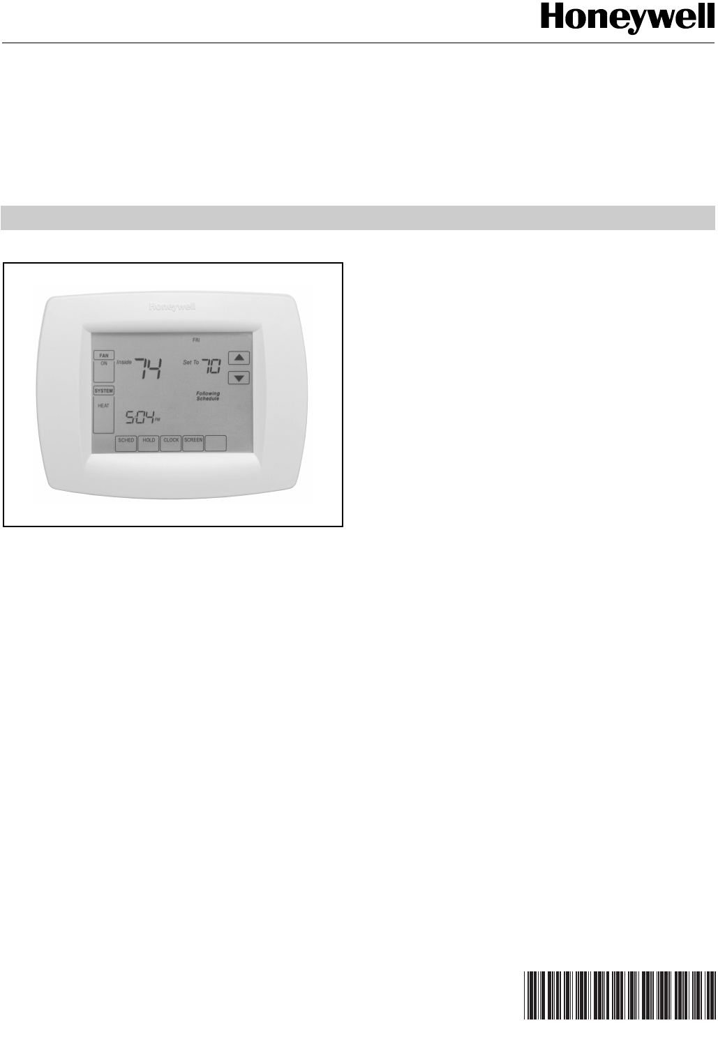
- VisionPRO™ 8000 Touchscreen 1
- Programmable Thermostat 1
- ORDERING INFORMATION 2
- SPECIFICATIONS 2
- 3 68-0280—01 3
- INSTALLATION 4
- Selecting Location 4
- Installing Wallplate 4
- WIRING (FIG. 9 - 21) 5
- NORMALLY OPEN 7
- VisionPRO 10
- Wiring 24 Vac Common 11
- Installing Batteries 11
- Mount Thermostat to Wallplate 11
- Temperature Sensor (Optional) 12
- Wire C7089U Outdoor Sensor 12
- Wire C7189 Indoor Sensor 13
- Set Calendar and Time 14
- INSTALLER SETUP 15
- 68-0280—01 16 16
- 17 68-0280—01 17
- 68-0280—01 18 18
- 19 68-0280—01 19
- INSTALLER SYSTEM TEST 20
- OPERATION 21
- 68-0280—01 22 22
- PROGRAMMING 23
- Edit Schedule 24
- Cancel a Schedule Period 24
- Fan Schedule 25
- Fan Control (Table 7) 25
- Set Time 26
- Set Temperature Overrides 26
- Clean Thermostat Screen 27
- Replace Batteries 28
- Battery Tips 28
- Screen Locks 28
- Outdoor Temperature 29
- Remote Indoor Temperature 29
- Indoor Air Quality Reminders 29
- 68-0280—01 30 30
- Temperature Recovery 31
- P+I Control 31
- Minimum Off-Timer 32
- COMPRESSOR ONLY 33
- FOSSIL FUEL ONLY 33
- Outdoor Temperature Sensor 34
- Operation in Heat Mode 34
- Operating Sequence 34
- 35 68-0280—01 35
- Operation 36
- Checkout 36
- Calibration 36
- Following 37
- Schedule 37
- TROUBLESHOOTING (TABLE 14) 38
- 39 68-0280—01 39
Summary of Contents
PRODUCT DATA68-0280-01® U.S. Registered Trademark© 2011 Honeywell International Inc. All Rights Reserved VisionPRO™ 8000 TouchscreenProgrammable Therm
VisionPROTM 8000 Touchscreen Programmable Thermostat68-0280—01 10Fig. 20. Typical hookup of single-stage heat pump with auxiliary/backup heat (2H/1C h
VisionPROTM 8000 Touchscreen Programmable Thermostat11 68-0280—01POWER THE THERMOSTATYou can choose from three methods to power the thermostat:• Batte
VisionPROTM 8000 Touchscreen Programmable Thermostat68-0280—01 12Locate and Mount C7089U Outdoor Temperature Sensor (Optional)Mount the sensor where (
VisionPROTM 8000 Touchscreen Programmable Thermostat13 68-0280—01Locate and Mount C7189U Remote Indoor Temperature Sensor (Optional)1. Choose a locati
VisionPROTM 8000 Touchscreen Programmable Thermostat68-0280—01 14Fig. 28. Wiring a single C7189 Indoor Sensor.Fig. 29. Wiring Multiple C7189 Sensors.S
VisionPROTM 8000 Touchscreen Programmable Thermostat15 68-0280—01INSTALLER SETUPFollow these steps to enter the Installer Setup:1. Press and release t
VisionPROTM 8000 Touchscreen Programmable Thermostat68-0280—01 16Table 3. Installer Setup Menu.Installer Setup Number Installer Setup Name Settings No
VisionPROTM 8000 Touchscreen Programmable Thermostat17 68-0280—010260 Cycles per hour (cph) for 3rd Stage Heat(Aux Heat for 3H/2C Heat Pumps)1—1 cph u
VisionPROTM 8000 Touchscreen Programmable Thermostat68-0280—01 180360 Heat Pump Auxiliary Lockout0—no auxiliary heat lockout.
VisionPROTM 8000 Touchscreen Programmable Thermostat19 68-0280—010650 Extended Fan OnTime Heat0—no extended fan operation after call for heat ends90—
VisionPROTM 8000 Touchscreen Programmable Thermostat68-0280—01 2ORDERING INFORMATIONWhen purchasing replacement and modernization products from your T
VisionPROTM 8000 Touchscreen Programmable Thermostat68-0280—01 20INSTALLER SYSTEM TESTUse the Installer System Test to test the heating, cooling and f
VisionPROTM 8000 Touchscreen Programmable Thermostat21 68-0280—01OPERATION Thermostat KeysThermostat DisplaySystem and Fan SettingsSystemThe System ke
VisionPROTM 8000 Touchscreen Programmable Thermostat68-0280—01 222. Press and hold the center blank key for approximately five seconds until the scree
VisionPROTM 8000 Touchscreen Programmable Thermostat23 68-0280—01PROGRAMMINGPreprogrammed Energy-saving SettingsTable 6 shows default program settings
VisionPROTM 8000 Touchscreen Programmable Thermostat68-0280—01 24Edit Schedule1. Press Sched key.2. Press Edit key.3. It is OK to pick multiple days.
VisionPROTM 8000 Touchscreen Programmable Thermostat25 68-0280—01NOTE: To reinstate a schedule period, press arrow keys to set desired time and temper
VisionPROTM 8000 Touchscreen Programmable Thermostat68-0280—01 26Manual Override of Fan Schedule (Table 8)Auto—fan is automatically following the Fan
VisionPROTM 8000 Touchscreen Programmable Thermostat27 68-0280—012. Press Up or Down arrow next to the Time key to set desired time for the thermostat
VisionPROTM 8000 Touchscreen Programmable Thermostat68-0280—01 28Replace Batteries1. When the LO Battery indicator is flashing, replace the batteries
VisionPROTM 8000 Touchscreen Programmable Thermostat29 68-0280—01Partially Locked ScreenWhen partially locked, the screen indicates Screen Locked for
VisionPROTM 8000 Touchscreen Programmable Thermostat3 68-0280—01Auxiliary Heat Indication: TH8000 VisionPRO™ Touchscreen Thermostats show “Aux. Heat O
VisionPROTM 8000 Touchscreen Programmable Thermostat68-0280—01 30The remaining run time days can be viewed by pressing the More key; the remaining day
VisionPROTM 8000 Touchscreen Programmable Thermostat31 68-0280—01Humidifier Pad ReminderThe Humidifier Pad change reminder must be turned on from the
VisionPROTM 8000 Touchscreen Programmable Thermostat68-0280—01 32Fig. 31. Proportional temperature control versus P+ I temperature control.Minimum Off
VisionPROTM 8000 Touchscreen Programmable Thermostat33 68-0280—01Control Dehumidification Setting (Select Models)Select models read the inside humidit
VisionPROTM 8000 Touchscreen Programmable Thermostat68-0280—01 34OPERATION IN EMERGENCY HEAT MODEThe balance point (outside) temperature is not used i
VisionPROTM 8000 Touchscreen Programmable Thermostat35 68-0280—01aConfigure O/B in Installer Setup. Based on last piece of equipment called (cooling =
VisionPROTM 8000 Touchscreen Programmable Thermostat68-0280—01 36C7089U Outdoor Temperature SensorOperationWhen installed with Thermostat Installer Se
VisionPROTM 8000 Touchscreen Programmable Thermostat37 68-0280—01C7189U Remote Indoor Temperature SensorOperationWhen installed with Thermostat Insta
VisionPROTM 8000 Touchscreen Programmable Thermostat68-0280—01 38TROUBLESHOOTING (TABLE 14)Table 14. Troubleshooting.Symptom Possible Cause ActionDisp
VisionPROTM 8000 Touchscreen Programmable Thermostat39 68-0280—01Heat pump puts out cool air in the heat mode and warm air in the cool mode.Changeover
VisionPROTM 8000 Touchscreen Programmable Thermostat68-0280—01 4Fig. 4. C7189U Remote Indoor Sensor dimensions in in. (mm).INSTALLATIONWhen Installing
68-0280—01 M.S. Rev. 03-11 Printed in U.S.A. www.honeywell.com/yourhomeAutomation and Control SolutionsHoneywell International Inc. Honeywell Lim
VisionPROTM 8000 Touchscreen Programmable Thermostat5 68-0280—014. Position the wallplate over the holes, pulling wires through the wiring opening. Se
VisionPROTM 8000 Touchscreen Programmable Thermostat68-0280—01 6NOTES:1. When used in a single-transformer system, leave metal jumper wire in place be
VisionPROTM 8000 Touchscreen Programmable Thermostat7 68-0280—01Fig. 11. Typical hookup of heat-only system (1 H conventional).Fig. 12. Typical hookup
VisionPROTM 8000 Touchscreen Programmable Thermostat68-0280—01 8Fig. 15. Typical hookup of cool only system (1C conventional).Fig. 16. Typical hookup
VisionPROTM 8000 Touchscreen Programmable Thermostat9 68-0280—01Fig. 18. Typical hookup of single-stage heat pump with no auxiliary/backup heat (1H/1C
Related products and manuals for Thermostats Honeywell VISIONPRO TH8320

 (56 pages)
 (6 pages)
(12 pages)
(6 pages)
(12 pages)
 (108 pages) (12 pages)
(64 pages)
(12 pages)
(12 pages)
(20 pages)
(108 pages) (12 pages)
(64 pages)
(12 pages)
(12 pages)
(20 pages)
© 2020, manymanuals.com. All rights reserved. | 0.681 s |
 Manymanuals.com
 Manymanuals.de
 Manymanuals.fr
 Manymanuals.it
 Manymanuals.pl
 Manymanuals.cz
 Manymanuals.es
 Manymanuals-pt.com
Comments to this Manuals